


Installation and Startup of Fleck 5600 and 2510 Backwashing Filters:
A Non-Technical Guide to Installing and Putting into Service the Pure Water Products Standard Backwashing Filters
Here are the steps involved in setting up and starting up your backwashing filter.
1. Check to make sure you have all the parts before you start.
2. Select your installation site and put the filter in place.
3. Load the media into the tank and screw on the control valve.
4. Connect the filter to your plumbing.
5. Run water into the filter and check for leaks.
6. Allow adequate time for the media to soak.
7. Backwash the filter, then run one or more full regeneration cycles.
8. Put the filter into service and start using the water.
Here’s an expansion of the steps presented above.
1. Parts List
You should receive:
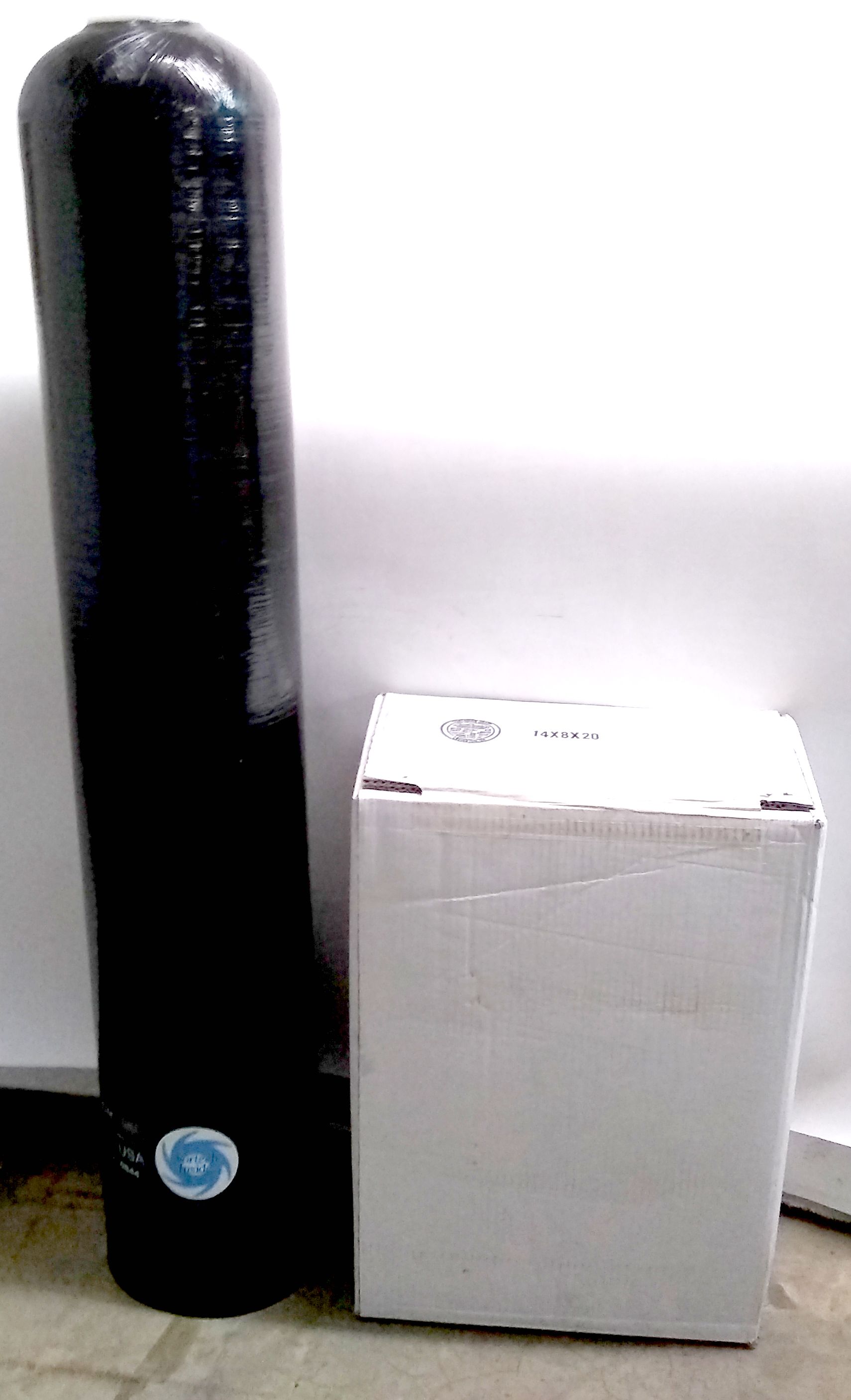
You should have a mineral tank and one or more boxes of filter media.
1. A large tank called a “mineral tank.” Most of our filters use Vortech (Enpress) tanks. There will be a tube called a “riser” or “dip tube” permanently installed in the tank and visible through the hole in the top. The tank size will be stated on a decal on the side of the tank near the bottom. “1054” means the tank is 10″ in diameter and 54″ tall, for example. “0948” means the tank is 9″ in diameter and 48″ tall. Note: If your tank leans to the side like the tank in the picture, it’s because it is crooked in its base. This sometimes happens during shipping. To fix it, just pick tank up, while it’s light and empty, and tap the base against the floor until you get it straight.
2. A box or multiple boxes of the filtration medium that goes in the tank. Be sure you have enough before you start. Media is commonly boxed in 1/2, 3/4, and 1 cubic foot sizes. Here are the common residential tank sizes and the media amount they hold:
0844 – 3/4 cubic foot.
0948 – 1 cubic foot.
1044 – 1.25 cubic feet.
1054 – 1.5 cubic feet.
1252 – 2.0 cubic feet.
1354 – 2.5 cubic feet.
Be sure you have enough, but if you got too much, don’t overload the tank.
Vortech mineral tanks require no gravel underbed, so the filter medium is all you will be putting into the tank. It should fill the tank about 2/3 full.
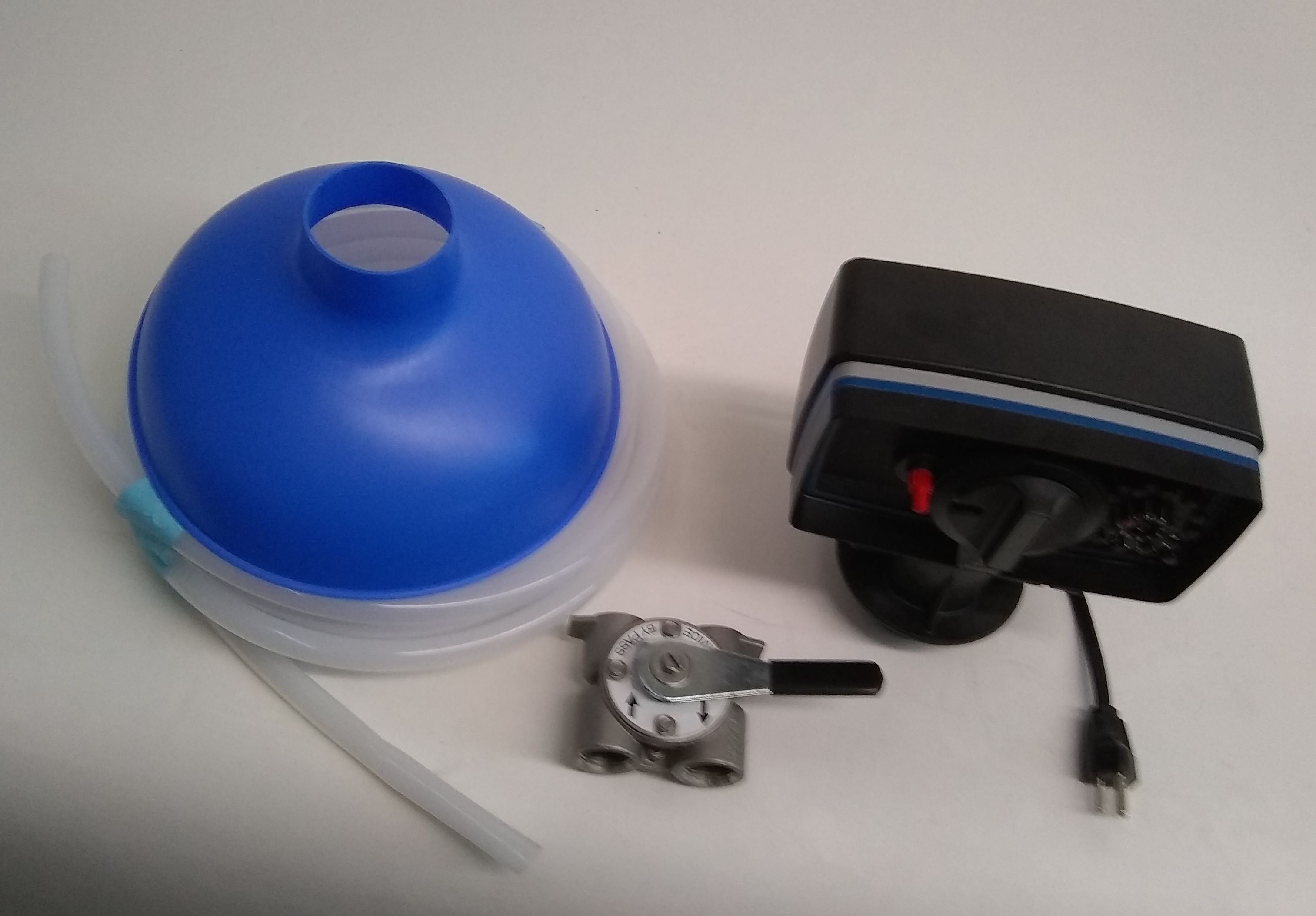
Funnel, drain tubing, stainless steel bypass valve, and filter control valve.
3. A blue funnel to pour the media in with.
4. A stainless steel bypass valve, with either 3/4″ or 1″ ports.
5. Drain tubing. In most cases, 25′ of flexible 1/2″ drain tubing. (No drain tubing is included with larger 2510 filters that require more than 7 gallons-per-minute drain flow.)
6. The control valve. It will be one of these listed below. (Fleck does not put product names on its control valves, but you can identify your control valve from our main website.)
5600 Electro-mechanical Timer
5600 SXT (Electronic timer)
5600 AIO (Electronic Aeration Timer)
2510 Manual (non-electric)
2510 Electro-mechanical Timer
2510 SXT Electronic Timer
2510 AIO (Electronic Aeration Timer)
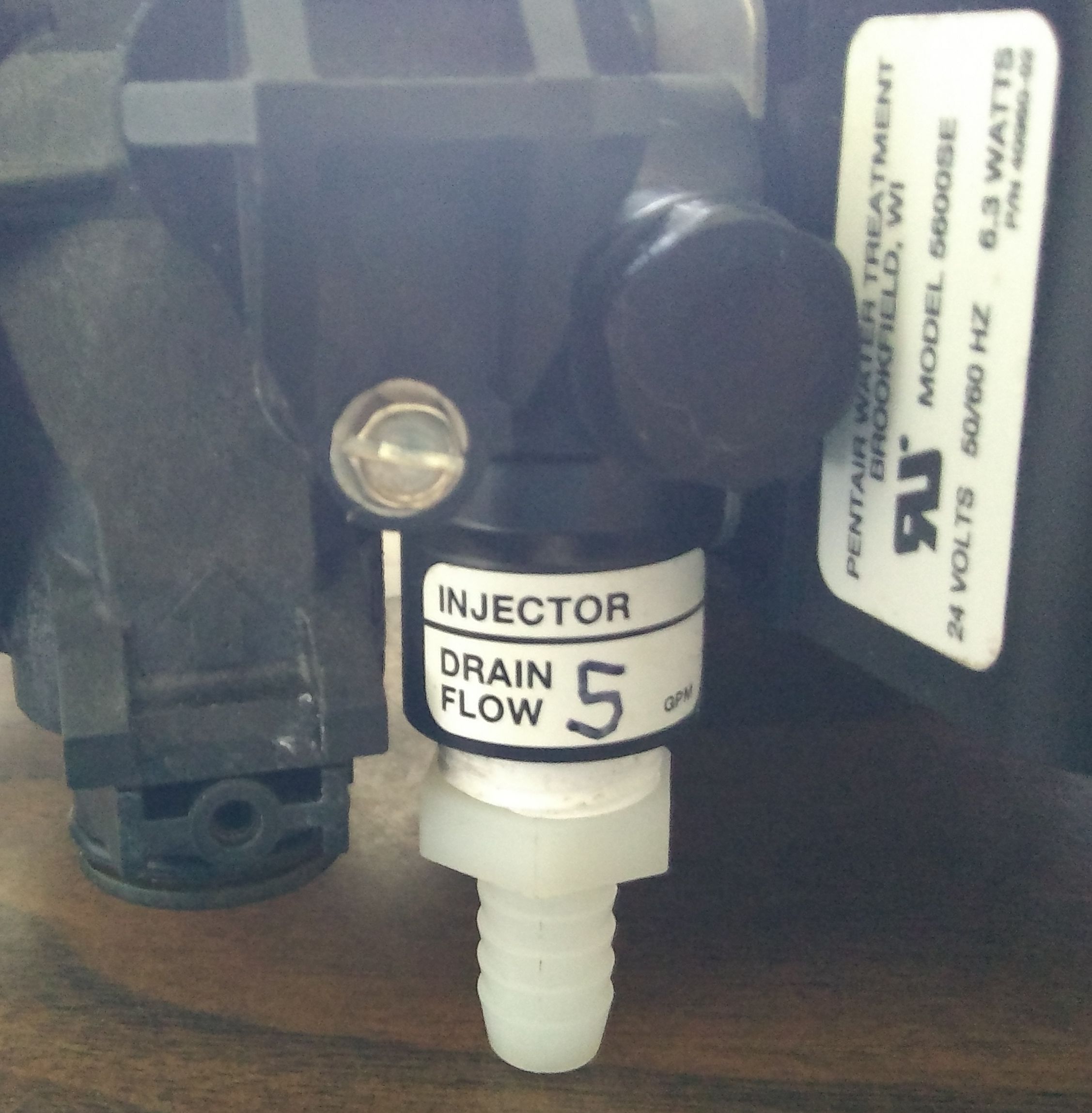
The control should have a tag near the drain port designating the flow control device installed in the filter. It will be one of these: 4, 5, 6, 7 gallons per minute. Fleck 2510 iron filters for larger tanks will have a metal drain line cartridge with the gallons per minute (gpm) rating stamped on the side.
2. Select a Place for Installation
The filter should be installed in a place where it will treat all the water going into the home. Usually, irrigation lines will be excluded. Most filters need access to a drain and a 110 volt electrical source. Drain water from a filter, unlike a water softener, is just water. So, if it is feasible, drain water can be directed to water plants. Keep in mind that the filter will at some time require maintenance and probably a media change, so put it in a place that gives you access. If installing outdoors, the filter will need protection from freezing, direct sunlight, and rain. Unless earthquakes are an issue, there is no need to secure the filter with straps, but it needs a good, solid, level surface to stand on.
3. Load the media into the tank and screw on the control valve.
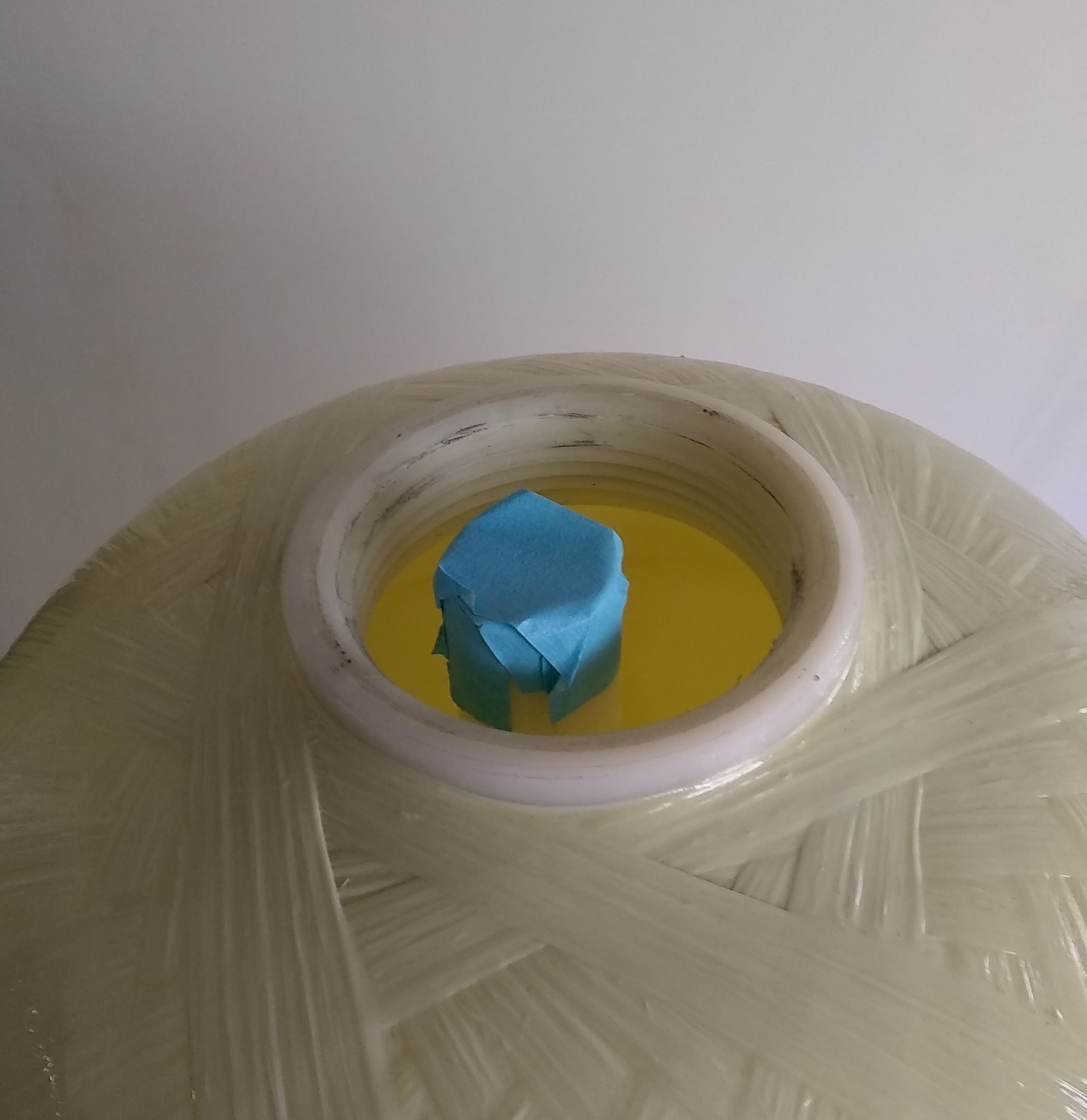
Put tape or a small plastic bag over the open end of the tank’s riser tube to prevent media from going into the tube. Don’t forget to remove the tape after the media is loaded. And clean any media dust out of the tank threads before screwing on the control head.
Using the funnel provided, pour all of the filter media into the tank. No gravel underbed is needed. Before you start, cover the top of the riser tube centered in the tank with duct tape or with a small plastic bag so that media cannot get into the tube. Media that goes into the tube will end up in your house lines. Filter media, especially carbon, are dusty, so it’s a good idea to wear a face mask while pouring media into the tank. The media will not fill the tank completely. In most cases, the tank will be about 2/3 full. When the granular filter medium has been loaded, clean the tank threads of media dust and screw the valve onto the tank. (The riser goes into the center hole of the bottom of the control valve.) Hand tighten until snug. No tool needed.
4. Connect the filter to your plumbing.
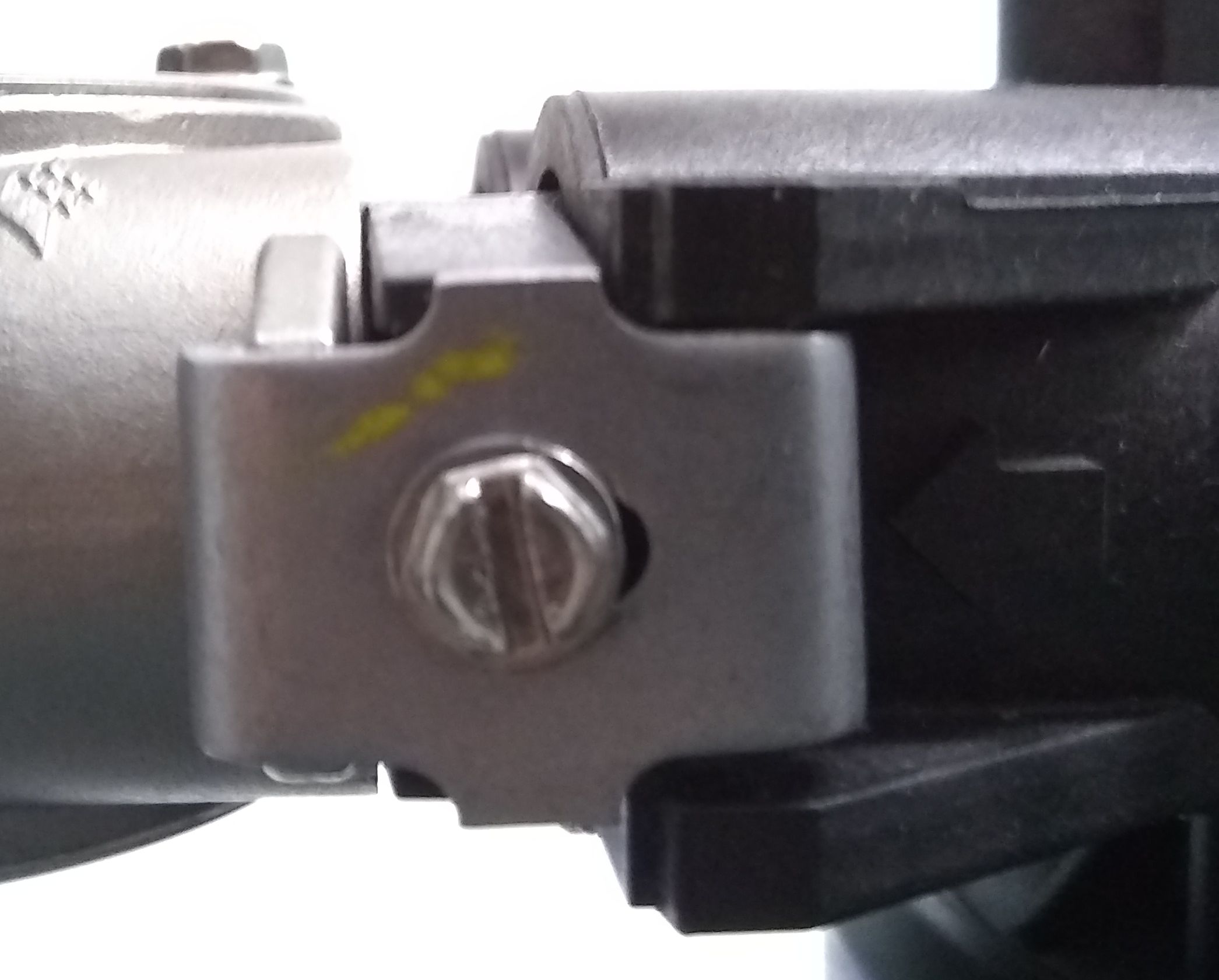 The bypass valve connects to the control valve body with clamps. A small amount of wiggle is normal after clamps are tightened.
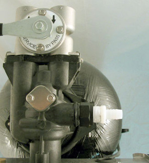
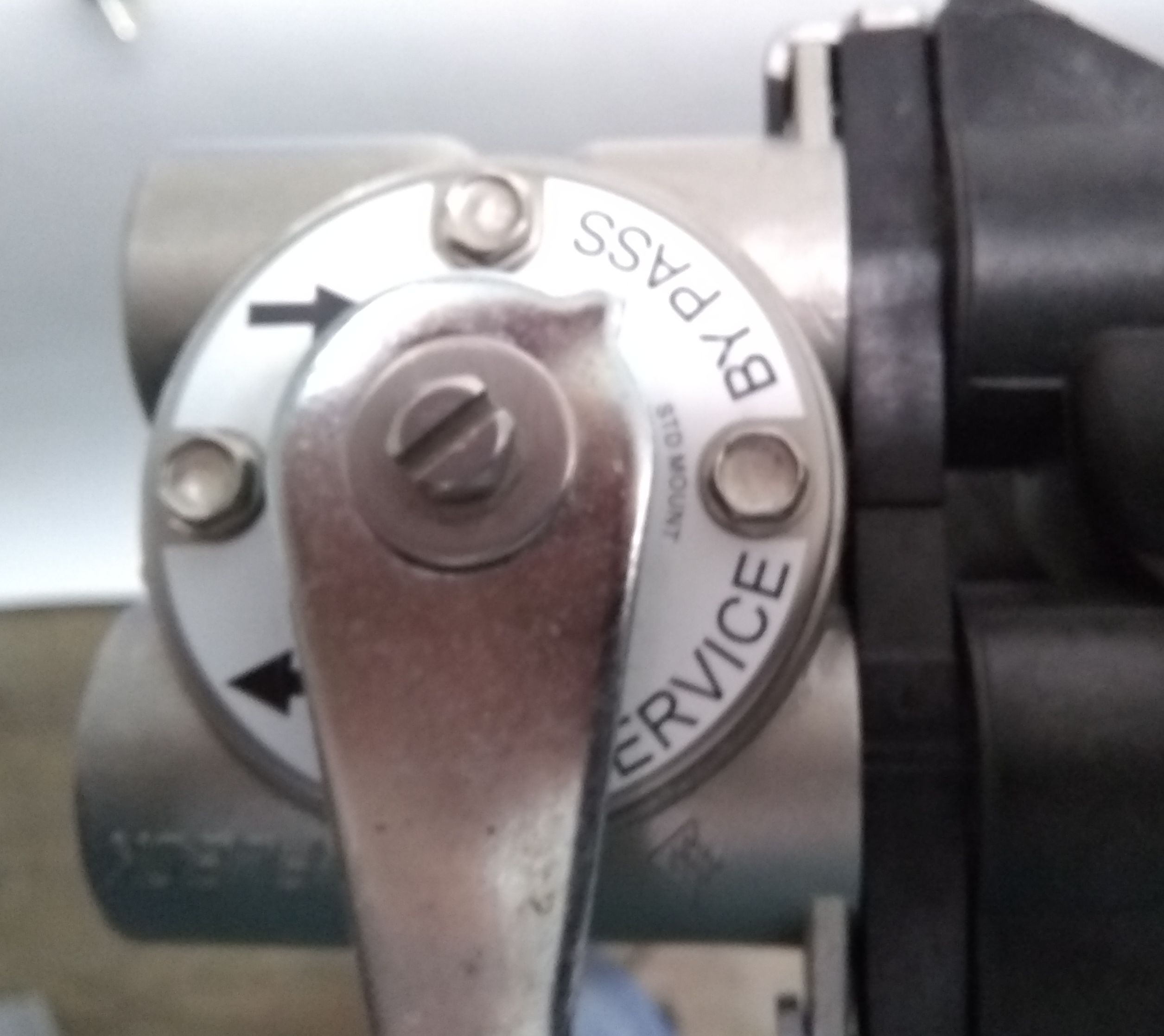
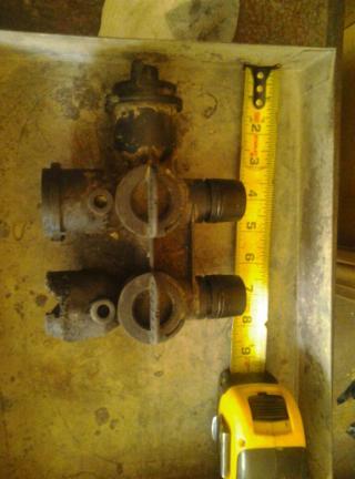
Fleck 2510 Control with Bypass installed. Note that the bypass valve is in bypass position. When in bypass mode, the valve sends water around the filter to the home. The “Service” setting sends water through the filter and to the home.
The stainless bypass connects to the o-ringed adapters and is secured by two clamps. Slide the bypass into place and tighten the clamps snugly. It is normal for there to be some “play” in the finished assembly.
The bypass ends in 3/4″ or 1″ female pipe thread. Connect to your plumbing using standard plumbing Teflon tape or liquid Teflon. (Teflon tape is what most installers use.)
Note that water enters the filter from the left (looking at it from the pipe installation side). Follow the directional arrows on the bypass.
Connect to a drain following your local plumbing code. The filter comes with flexible tubing that slips onto the barbed fitting on the control. (Adding a hose clamp is recommended.) If you prefer to hard-pipe the drain, remove the barbed fitting and connect to the female thread.
We highly recommend installing a shutoff valve in the pipe coming into the filter.
5. Run water into the filter and check for leaks.
Put the bypass valve in back of the filter into Service position.
Plug in the control valve.
Before sending water into the filter, it’s best to put the control valve into Backwash mode. This will allow water to flow upward through the filter and out the drain line, protecting the home’s service lines from debris coming from the unwashed media.
Here’s how to put the control valve into backwash position:
For mechanical timer valves (no digital display), turn the large center knob on the timer face clockwise. With the 2510, click the center knob one click and you will hear the motor engage. Allow a minute for the piston to move into place and the unit will be in backwash position. With the 5600, advance the knob slowly clockwise a few clicks until you see the beginning of a word in the viewing slot. Wait one minute, then unplug the valve.
For SXT electronic control valves, push the button on the left side of the face and hold for five seconds or until you hear the motor engage. Wait for the motor to move the valve to backwash mode. When “BW” shows on the display and the time (e.g. 10:00) begins counting down backward.
When the valve is in backwash position, unplug the valve.
The unplugged valve will remain in backwash position.
Open the water inlet valve halfway and allow water to slowly fill the tank. Take your time.
When the tank is full and water is running smoothly (but slowly) from the drain line, turn off the water and allow the media to soak.
6. Allow adequate time for the media to soak.
During the media soak, placing the bypass valve into Bypass position will send unfiltered water into the home.
There are no hard rules about how long the media should soak. Half an hour is enough for most media. Some manufacturers ask for a longer soak:
Zeolite –24 hours.
Carbon – 24 hours.
Katalox Light – Overnight soak and extended backwash.
In addition to media loss, the consequences of inadequate soaking can be excess air in service lines (especially with carbon), small particulate in service lines, cloudy water for a time, and sometimes a metallic taste. Initial service water with Katalox Light is unpredictable: sometimes it puts out a fine film that lasts for days, sometimes a metallic taste, and it almost always produces high pH and high alkalinity. These issues eventually go away.
7. Backwash the filter, then run a full regeneration cycle.
After the media has had a good soak, return the bypass valve to service position, open the inlet valve all the way and plug the control valve in. The backwash will resume, now at full speed. Let the control valve finish the entire cycle (backwash and rinse). Note that mechanical timers take much longer to return to service than SXT units. With mechanical valves, after the rinse has finished, it’s permissible to advance the valve manually to service position.
Finally, open the downstream faucet nearest the filter and let water rinse from the faucet at least ten minutes. The water should run completely clear.
If you feel that more backwash and rinse are needed, simply repeat the regeneration cycle.

